Rock and Sediment Mechanics Laboratory
The Pennsylvania State University
Apparatus
The Penn State Rock & Sediment Mechanics Laboratory is equipped to carry out consolidation permeability, friction, shear, and fracture studies under a wide range of experimental conditions. Permeability and deformation measurements are carried out both in traditional triaxial systems and high-stress uniaxial consolidation and permeability systems developed by Saffer, and in a true-triaxial pressure vessel developed by Marone. Friction experiments and those related to the science of earthquakes are carried out in a biaxial testing apparatus constructed by Marone. Recent hardware developments also allow for measurement of elastic wave propagation through core samples and sheared layers in all of the experimental configurations. Research in rock mechanics and earthquake physics benefits significantly from ongoing work in seismology, tectonics, geodynamics, and geo-environmental engineering at Penn State. A network of Macs running OS X and Linux machines are available for data analysis and acquisition.
Uniaxial Deformation Frame
For uniaxial deformation experiments, the sample cell is a high-pressure fixed-ring oedometer vessel designed jointly by Saffer and GDS Instruments Ltd. It consists of a cell base and top, which bolt together at a mid-point allowing for easy sample insertion and access. The vessel includes two fluid ports at the top, and two at the base. One pressure/volume controller (GDS design) is connected at the top and the other at the base – in order to conduct singly or doubly drained consolidation experiments and flow-through permeability measurements. The sample cell is rated to 10 MPa internal pore pressure. Sintered porous discs are emplaced in machined recesses in the ram cap and cell base. The ram inserts through a guide tube and seals (viton low-friction o-rings) that hold pore pressure and fluid volume inside the vessel. Recent modifications to the system for permeability measurement on hard-rock samples include top and base gaskets and design of sample rings specifically machined to match the sample diameter and which include a central o-ring seal at the sample mid-point; these adaptations have worked well on outcrop and SAFOD drill hole samples. Such measures are unnecessary for typically more compressible sedimentary rocks or fault zone materials, which self-seal against the sample ring under axial load [e.g., Saffer and McKiernan, 2005].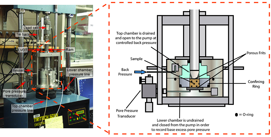
Back to Top
Biaxial Deformation Press
 Friction experiments are performed primarily using the double-direct shear geometry in a biaxial load frame. Load axes are precisely perpendicular, and surfaces of frictional shear are oriented such that normal and shear tractions are controlled independently. Each load frame of the biaxial apparatus consists of stiff steel platens connected by precision cut steel rods. The vertical ram is fitted with a 10-inch bore, 6-inch stroke hydraulic ram capable of producing forces up to 1 MN. The horizontal ram is capable of forces up to 670 kN. The apparatus is capable of accepting samples with nominal frictional contact dimensions up to 30 cm x 30 cm. Steel blocks are used to support samples at a position precisely aligned with the center of the horizontal and vertical load axes. Steel platens also buttress the side blocks of the friction sample to eliminate rotational motion induced by direct shear. All steel work is precision ground flat, parallel, and square.
The apparatus was designed to be stiff so that details of friction and fracture can be measured without violent unstable failure. The nominal stiffness of each frame is measured by replacing the friction sample with solid steel. For forces in the range 0 to 500 kN, stiffnesses of the vertical and horizontal frames are 0.45 kN/µm and 0.33 kN/µm, respectively. Stiffness increases non-linearly at low loads, and these values are 10-15% larger at the upper end of this force range. For friction experiments, precise calibrations are carried out using a relaxation technique and transducers mounted directly on the friction sample). For results discussed in this paper, stiffnesses are 0.50 and 0.37 ±0.02 kN/µm for the vertical and horizontal frames, respectively. Expressed as stresses on surfaces with nominal contact area of 10 x 10 cm2, and accounting for the factor of two vertical force needed to shear two surfaces, the stiffnesses are 250 MPa/cm and 370 MPa/cm for shear and normal stresses, respectively.
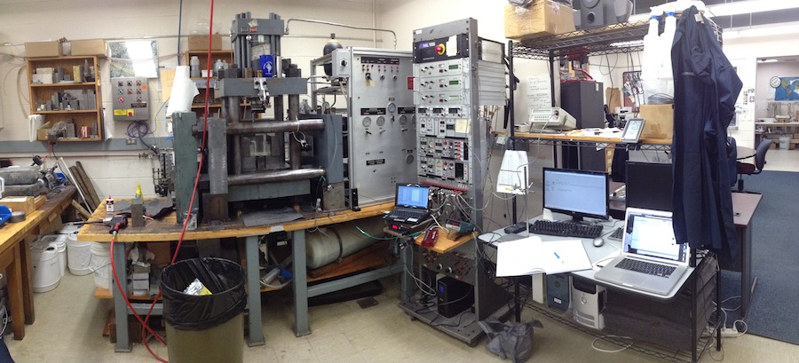
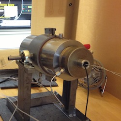
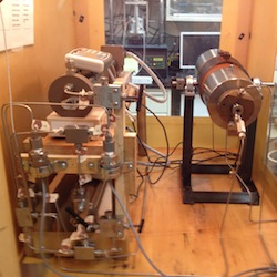
True-Triaxial Testing Apparatus & Double Direct Shear Under Hydrothermal Conditions The true-triaxial apparatus consists of 10,000-PSI pressure vessel (Figure 3) fitted in a servo-controlled biaxial load frame shown above. Measurements of along-fault and across-fault permeability can be carried out in the double-direct shear and single direct shear geometry. The machine is designed for friction, fracture, flow, and deformation experiments under fully-controlled conditions. Each axis of triaxial loading can be applied with force or displacement boundary conditions. Porosity, permeability, and pore fluid volume changes are measured during deformation. Samples can be deformed under drained or undrained loading conditions. Capabilities include double-direct shear and single-direct shear of granular and clay rich simulated fault gouge, natural fault gouge, bare rock surfaces in frictional contact, and in-situ shear fracture of intact samples.
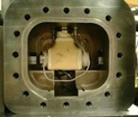
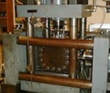
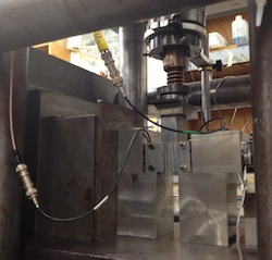
The pressure vessel has removable doors to allow sample access and set-up of electrical and fluid connections (Figure 3). Fluids enter through the platens and access the sample via porous frits (Figure 4). A flexible latex jackets separates pore and confining fluids. Pore-pressure (Pp) and confining pressure (Pc) intensifiers are designed for pressures to 10,000 PSI with a volume of 155 cc. The system is capable of resolving volume changes as small as 1×10⁻⁴ cc. Biaxial applied stresses (heavy arrows in Figure 4a) of up to 300 MPa can be applied.
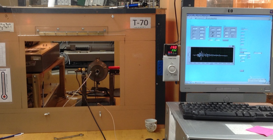
We have also developed a system for measuring acoustic velocity/elastic wave properties and passive acoustic emissions within the biaxial testing machine and double direct shear configuration. The system makes used of pin-type PZT’s (pinducers), used primarily in passive detection mode, and larger (1” diameter) PTZ’s used in both ‘active source’ and ‘passive’ mode. The PZT’s are embedded in specially designed sample grips in the double direct shear configuration (see Figure below). The system is capable of accepting P- and S-mode PZT transducers and can measure one-way travel time through the samples, using established first arrival and waveform correlation techniques (“time-of-flight”), similar to the approach described above for core samples. PZT crystals with low center frequencies are driven by a high voltage (900V) signal generator.
Triaxial Deformation Rigs
For triaxial experiments, four cells are available for confining pressures up to ~100 MPa and temperatures up to 150 C. The vessels are interchangeable within the load frames, but differ slightly in their construction. All have several ports for fluid or electrical lines to pass into the vessel, and to allow simultaneous measurement of permeability and ultrasonic wavespeed. In our experiments, samples are typically jacketed in latex or viton, with o-ring seals at the top and base of the sample, and silicon oil is used as a confining fluid.
In typical configuration, both the top and base of the sample are plumbed to pressure/volume controllers, to maintain sample pore pressure and to allow permeability testing. A third pressure/volume controller can be used to maintain confining pressure, and to monitor volume changes of the confining fluid related to sample dilation or consolidation. We also measure the volumetric strain using the external LVDT for axial deformation and the radial strain caliper equipped with a submersible LVDT. Any desired stress path within the apparatus maximum pressure and stress capability can be achieved under (1) stress feedback control (controlled mean and differential stress, resulting strain is monitored), (2) strain control (controlled shortening rate and/or rate of volume change, resulting stresses are monitored), or (3) manual control.
Measurements of permeability can be carried out in any of the testing systems, using either flow-through (steady-state), or transient (sinusoidal loading or pulse decay) techniques. Flow (or pressure) for permeability tests is controlled by high-precision flow pumps plumbed to the upstream and downstream ends of the sample. Flow through tests can be conducted in concert with ultrasonic measurements of Vp and Vs along the core axis. This is achieved by using modified end-caps for fluid distribution that include 1/2” diameter 500 kHz lead zirconate titanate (PZT) shear-wave transducers embedded within a “well” in each end cap. PZT crystals cut in a shear orientation also produce a small P-wave at a similar center frequency and can be excited by an arriving P-wave. This allows us to use the shear wave crystals to measure both P and S waves simultaneously. Velocity is measured in direct time-of-flight mode, using a 900-volt negative impulse as a source pulse with a repetition rate of 100 Hz. The recording frequency is 25 MHz, and each saved waveform is made up of 100 stacked waveforms. The system is also equipped for measurement of electrical resistivity in conjunction with permeability tests, using modified insulated end-caps (however, resistivity and velocity measurements cannot be conducted simultaneously in the system as currently configured).
The High Pressure High Temperature Laboratory houses four standard triaxial vessels capable of deviatoric and confining stresses to 100 MPa on 25 mm diameter samples and similar fluid pressures. High precision pumps are capable of applying confining pressures, deviatoric stresses and fluid pressures. Simultaneous deformation and permeability may be completed at temperatures to ~150C and with liquids or gases as the permeants. Permeability measurements are made as steady "Darcy" tests for moderate permeability materials (>mD) and as pulse tests for low permeability materials (< mD). The systems are equipped with a gas chromatograph to measure multi-component sorption, desorption and swelling response of sorbing media such as coals and shales. Some of the systems are housed in environmental chambers that control temperature to within +/- 0.1 C, in order to minimize the effects of thermally-induced volume changes on fluid flow and deformation measurements. Pore volume change is measured to +/- 1 mm3 (1 µl), displacement is measured to +/- 0.5 µm, displacement rate is controlled to a precision of +/- 10-2 µm min–1, and stress is measured/controlled to a precision of +/- < 1 kPa.